The importance of selecting the correct antenna
An RFID antenna is a necessary part of any RFID system making antenna selection a critical part of the process. If you don’t select the correct antenna for your specific needs, you run the risk of the entire solution being unsuccessful losing time and money! We don’t want to see that happen! Let’s take a closer look at the IEEE poster and how you can use it to help determine how many and which Times-7 antenna you might need.
What are radiation patterns?
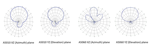
The radiation pattern is a graphical representation of the antenna’s radiated power in a three-dimensional space at far-field distances. It can also be plotted in two-dimensional spherical coordinates. The examples in Fig.1 below represent the azimuth and elevation planes using a polar chart. Azimuth and elevation planes plot the 2-D radiation pattern of the antenna or array object over a specified frequency.
Antennas follow the principle of reciprocity meaning that the radiation pattern holds true for both transmitting and receiving antennas.
Times-7 antenna radiation pattern:
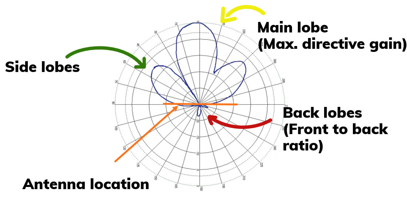
The antenna’s radiation angle or the width of the beam is termed as the beamwidth [Fig.2]. Half Power Beamwidth (HPBW) angle is calculated between the half-power (3dB) points of the main lobe. Wide beam antennas are low gain in nature compared to narrow beam antennas that have higher gain. The radiation pattern determines the ability to detect tags in a given area. The maximum directive gain of an antenna lies within the peak of the main lobe radiation. Side lobes are minor lobes found on the sides of the main lobe. The ratio between the magnitude of the main lobe and the back lobe is known as the antenna’s front to back ratio [Fig. 3].
[Fig. 2]
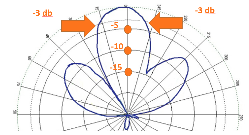
[Fig. 3: Half Power Beamwidth (HPBW) angle is calculated between the half-power (3dB) points of the main lobe]
Calculation for theoretical read coverage
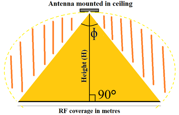
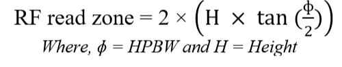
The antenna’s RF coverage can be determined for a specific distance with the HPBW angle. Using trigonometry, we can use the formulated equation to determine the RF read zone. The yellow triangle represents the high tag detection probability. You will also read tags in the orange region, but they may require a little extra power. There are good calculators online, that do the math for you, making this part a lot easier. Click here to access the online calculator.
The following table shows read zone estimations for selected Times-7 antennas using the calculation above.
| Commercial Antenna Model Number |
Elevation (YZ Plane) |
Azimuth (XZ Plane) |
||
| HPBW | ~Read Zone | HPBW | ~ Read Zone | |
|
Times-7 A5010 |
68° |
3.2m |
68° |
3.2m |
|
Times-7 A5020 |
~100° |
5.7m |
~100° |
5.7m |
|
Times-7 A5060 |
25° |
1m |
60° |
2.7m |
Read zones in real-world environments
Although the data in the table above provides a good estimation of the antenna's read coverage it does not reflect its performance in a real-world environment. That is due to the following elements, which impact the antennas’ read performance and therefore have to be taken into consideration:
- Reader power setting
- Cable losses
- Tag sensitivity
- Tag antenna's radiation pattern
- Multi-path reflections
That shows that System Integrators can't avoid testing an antenna using tagged assets in a close-to-real environment. However, testing the wrong antenna cost time and effort and potentially the end-customer as they may lose confidence in the technology. That is why being able to interpret the radiation patterns and determine the theoretical read coverage will give the System Integrator confidence to select the correct antenna for further testing, which will most likely meet the RF requirements.
3 steps to the read coverage:
We recommend the following steps below to ensure optimal accuracy when choosing the antenna.
1. Start by looking at the beam shape: We recommend that customers start by looking at the beam shape when selecting a suitable antenna.
Tip: In case of a stray tag-read concern, opt for narrow beam antennas! For help refer to our antenna selection guide here. This tool will calculate the maximum coverage that the antenna will cover from a specified distance and antenna's half-power beamwidth.
2. Use the theoretical calculation to determine the rough number of antennas needed to cover the wanted read zone. The theoretical calculation can also help determine the antenna model.
Tip: Once the antenna is selected, you have to take the factors that we listed above into consideration.
3. Test the antenna with the tag you intend to use for your application: For this step, a pilot in a real test environment is indispensable.
Tip: Use tagged assets vs tags in free space!
Testing Configuration:
The radiation pattern can be measured in a controlled environment using a reference antenna. In order to do a pilot test, you will need to:
- Take into account environmental reflections
- Test in a non-anechoic environment
For our own experiment the RFID read zone was mapped on A5010 and A5060 antennas by moving an Avery Dennison AD-237 Monza-R6P tag in 100 mm steps along their boresight’s elevation and azimuth axis to plot the maximum read distance. Mapped read zones conform with the radiation patterns of respective antennas. We will go into more detail in a future blog post on how we carried out an effective read zone test.